- Subscribe to RSS Feed
- Mark Topic as New
- Mark Topic as Read
- Float this Topic for Current User
- Bookmark
- Subscribe
- Mute
- Printer Friendly Page
Question on " Set DigitalPin Mode "
01-16-2012 02:32 PM
- Mark as New
- Bookmark
- Subscribe
- Mute
- Subscribe to RSS Feed
- Permalink
- Report to a Moderator
Hello
I have finished designing a Multiplexer Shield which help us to scan our Nano Structured Bio Sensors at U of T.
Let me tell you about this shield. and application which goes with it using Arduino Mega 2560.
Digital Output pins: 22 to 41
There are 20 digital pins which connected to series of analog switches... which makes a Multiplexer for our device.
Digital Output pins 2 and 3 connected to test LED
Digital Input pins: 46 to 53 ( these pins need to be read only once at the beginning of my VI )
I am using 8 digital pins as an serial number input ( read only High or Low values ) this will produce a serial number for each shield ( each pin is connected to pull up or pull down resistor ).
Digital Input pin: 10, This pin is very important for my application. I need to constantly read this pin; if the value changes, then I have to switch Digital Output pins.
What is the best way to set above digital channels at once ?
Do I have to modify Firmware ?
Is there a way to set combination of digital channels on Arduino Mega ?
Please tell me if there is any example that can help me.
I have Labview 2010
My OS is Vista,
Arduino board is Mega 2560
LIFA version is 2.0.0.67
Thanks a lot,
Hooman
01-16-2012 03:09 PM
- Mark as New
- Bookmark
- Subscribe
- Mute
- Subscribe to RSS Feed
- Permalink
- Report to a Moderator
Hi Hooman,
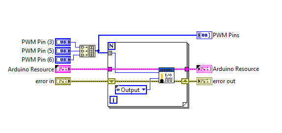
The best way to set your digital channels is to use a for loop to set the pins one by one. Due to the fact that the ATMega is a single-core CPU, it can only due one thing at a time. As such, you cannot set all the digital channels at exactly the same time. See the screenshot below to see how to set multiple pins. This is taken from the PWM Configure Port VI.
Hope this helps,
- Julianne
Systems Engineer, Embedded Systems
Certified LabVIEW Architect, Certified LabVIEW Embedded Systems Developer
National Instruments
01-17-2012 11:12 AM
- Mark as New
- Bookmark
- Subscribe
- Mute
- Subscribe to RSS Feed
- Permalink
- Report to a Moderator
Thanks Julianne for yor suggestion ...
That helped my to setup digital output.
New problem is as follwo:
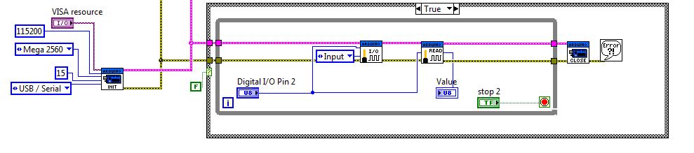
I can not set any digital outputs to " Read value" . can anybudy help?
I have Arduino Mega 2560. I use windows Vista and following is how I try to access digital pin "read". LIFA firmware is 2.0.0.67 ( no changes done to firmware )
I connected a 1k Ohm resistor to 5V or ground and connect this resistor to digital pin " 48 " or any other digital pins. There is no luck to read value from it that digital channel. How ever I can set any digital channels to output and turn on/off LEDs.
How can I make this work?
Thanks,
Hooman
....
01-17-2012 05:55 PM
- Mark as New
- Bookmark
- Subscribe
- Mute
- Subscribe to RSS Feed
- Permalink
- Report to a Moderator
Hey Hooman,
Take a look at the last post in this forum:https://decibel.ni.com/content/thread/11462?start=15&tstart=0
I just found this bug in the LIFA 2.0 firmware today.
Principal Software Engineer
NI
01-18-2012 02:25 PM
- Mark as New
- Bookmark
- Subscribe
- Mute
- Subscribe to RSS Feed
- Permalink
- Report to a Moderator
Hello Kevin
This is the way i fixed this bug in Arduino 1.0 IDE.
I open the sketch "LIFA_Base.ino" . then I opened " LabVEWInterface.ino "
go to section
| /********************************************************************************* | |
| ** Low Level - Digital I/O Commands | |
| ********************************************************************************* |
then I changed "serial.write('0') " to "serial.print('0') " . in other word I've changed all ".write " to ".print "
This fixed my issue with digital read.
Now my questions:
Should I change all ".write " commands to ".print " ?
Where can we find the LIFA 2.0 patch ?
Thanks,
Hooman
01-18-2012 02:46 PM
- Mark as New
- Bookmark
- Subscribe
- Mute
- Subscribe to RSS Feed
- Permalink
- Report to a Moderator
Hey Hooman,
I don't think you are going to want to change those everywhere. I haven't released a patch for LIFA 2.0 for that issue yet. I did post the fix on the forum above. All the rest of our commands use a similar method as what I posted to read back data from the Arduino so they should be good with the serial.write().
Principal Software Engineer
NI
