- Subscribe to RSS Feed
- Mark Topic as New
- Mark Topic as Read
- Float this Topic for Current User
- Bookmark
- Subscribe
- Mute
- Printer Friendly Page
Simulating NI USB-6001 using NI MAX
Solved!02-10-2024 10:52 AM
- Mark as New
- Bookmark
- Subscribe
- Mute
- Subscribe to RSS Feed
- Permalink
- Report to a Moderator
I'm taking a Udemy course on LabView currently working in a Section on NI-DAQmx Python API. This course requires using a USB-6001 data acquisition module to test their suggested code.
I've watched several other YouTube videos on creating and configuring "Simulated Devices" with NI MAX. However, their examples simulate the NI cDAQ-9174, NI 9205, and NI 9375 which worked fine for their example. However, I tried to create a new Simulated Device for the NI USB-6001 device and it would not allow me to Configure Simulated cDAQ device. It only showed me a Configure Hardware Device which I don't have any hardware.
So, is there a way to simulate and configure a NI USB-6001 device or is there a cDAQ device close to functionality, configuration, etc. that can be used to simulate a NI USB-6001 device? Are there instructions on how to achieve this device simulation?
Thanks, JT
Solved! Go to Solution.
- Tags:
- NI USB-6001
02-10-2024 06:42 PM
- Mark as New
- Bookmark
- Subscribe
- Mute
- Subscribe to RSS Feed
- Permalink
- Report to a Moderator
@Tesi2023 wrote:
So, is there a way to simulate and configure a NI USB-6001 device or is there a cDAQ device close to functionality, configuration, etc. that can be used to simulate a NI USB-6001 device? Are there instructions on how to achieve this device simulation?
Thanks, JT
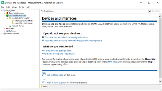
Do you have LabVIEW and MAX? Here is what MAX shows me ...
Bob Schor
02-11-2024 08:20 AM - edited 02-11-2024 08:23 AM
- Mark as New
- Bookmark
- Subscribe
- Mute
- Subscribe to RSS Feed
- Permalink
- Report to a Moderator
Bob_Schor,
Thanks but I've already tried exactly what you suggested and it did not provide me with a Simulated Configuration tab, it only provided a Hardware Configuration tab which means I would need actual USB-6001 hardware. I clearly stated I do not have any hardware in my original post.
Any other ideas on how to simulate the USB-6001?
Thanks, John
02-11-2024 08:28 AM
- Mark as New
- Bookmark
- Subscribe
- Mute
- Subscribe to RSS Feed
- Permalink
- Report to a Moderator
@Tesi2023 wrote:
Bob_Schor,
Thanks but I've already tried exactly what you suggested and it did not provide me with a Simulated Configuration tab, it only provided a Hardware Configuration tab which means I would need actual USB-6001 hardware. I clearly stated I do not have any hardware in my original post.
Any other ideas on how to simulate the USB-6001?
Thanks, John
John, the 6001 is a straight stand-alone DAQ device and does not operate as part of a cDAQ system. This is why you are getting your error. Simulated a USB-6001 the way Bob Schor shows under the "New>>Simulated device " menu.
"Should be" isn't "Is" -Jay
02-11-2024 08:51 AM
- Mark as New
- Bookmark
- Subscribe
- Mute
- Subscribe to RSS Feed
- Permalink
- Report to a Moderator
Knight of NI,
Here are the steps I used to create a Simulated USB-6001.
1. From the NI MAX main window, I RT+CLK the selected Devices and Interfaces
2. Create New and select Simulated NI DAQmx Device...> CLK Finish button
3. Expand USB DAQ folder and Select USB-6001 > CLK OK button
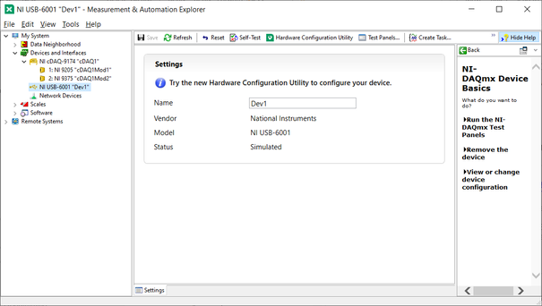
4. Select the newly created NI USB-6001 "Dev1" device that shows Hardware Configuration Utility tab.
5. Note when I select the previously created NI cDAQ-9174 "cDAQ1" device, it has a Configure Simulated cDAQ Chassis...
So, how exactly do I create a Simulated USB-6001 device that actually has a Configure Simulated USB-6001?
Thanks for your patience,
John
02-11-2024 10:57 AM
- Mark as New
- Bookmark
- Subscribe
- Mute
- Subscribe to RSS Feed
- Permalink
- Report to a Moderator
John, a Compact DAQ ("cDAQ") chassis can't contain a USB-6001. Only cDAQ modules have an interface that can be used in a cDAQ chassis and, cDAQ modules need a cDAQ chassis to work. An NI USB-6001 connects directly to a computer via USB and does not have a cDAQ interface.
A simulated NI USB-6001 needs no hardware configuration page because it needs no other hardware. Whereas, a cDAQ module does need a hardware configuration page because it has to be part of some cDAQ system.
Clear?
"Should be" isn't "Is" -Jay
02-11-2024 04:00 PM - edited 02-11-2024 04:02 PM
- Mark as New
- Bookmark
- Subscribe
- Mute
- Subscribe to RSS Feed
- Permalink
- Report to a Moderator
@Tesi2023 wrote:
So, how exactly do I create a Simulated USB-6001 device that actually has a Configure Simulated USB-6001?
Not! Since there is nothing to configure on an USB-6001 device. It contains 8 analog inputs, 2 analog outputs and 3 digital ports with in total 13 digital IO lines. There is no way to add any other hardware or remove anything from it. It is what it is and that is it.
A cDAQ chassis in itself has no IO hardware that you can control with DAQmx. Instead you plugin C modules but you can select from a few dozen of them depending on your needs. Here the simulated hardware interface for the cDAQ chassis lets you configure what C modules you want to have simulated in the various slots. The USB-6001 has no slots that you could configure by plugging in different modules.
02-11-2024 04:59 PM
- Mark as New
- Bookmark
- Subscribe
- Mute
- Subscribe to RSS Feed
- Permalink
- Report to a Moderator
Jay,
It is clear now about not requiring any configuration of a simulated USB-6001 according to your response.
So, I ran the following python version 3.12.1 code:
# Section 7 DAQ Programming Using Python
# Tutorial 137 Analog Read using Python
# filename: Analog_Read.py
# Python 3.12.1
# J. Trites, February 7th, 2024
# Simulated - Model = NI USB-6001, Name/Channel = 'Dev1/ai0'
import nidaqmx
with nidaqmx.Task() as task:
task.ai_channels.add_ai_voltage_chan('Dev1/ai0')
value = task.read()
print(value)
task.stop
And, here is the result:
Python 3.12.1 (tags/v3.12.1:2305ca5, Dec 7 2023, 21:47:43) [MSC v.1937 32 bit (Intel)] on win32
Type "help", "copyright", "credits" or "license()" for more information.
= RESTART: C:\Users\JohnTrites\Documents\Python and LabView Integration\Section7_DAQ\pycode7DAQ\Analog_Read.py
-0.07447198144304724
My only question left is how did this simulated USB-6001 come up with a negative analog value and how would I connect a simulated source voltage with range ? to generate simulated varying DC voltage values?
Thank you for your patience in walking me through this problem.
Best Regards,
John Trites
02-11-2024 05:30 PM
- Mark as New
- Bookmark
- Subscribe
- Mute
- Subscribe to RSS Feed
- Permalink
- Report to a Moderator
@Tesi2023 wrote:
My only question left is how did this simulated USB-6001 come up with a negative analog value and how would I connect a simulated source voltage with range ? to generate simulated varying DC voltage values?
Thank you for your patience in walking me through this problem.
Best Regards,
John Trites
NI DAQmx simulates a sinewave for simulated devices, and you have no control over its amplitude and frequency. Always remember "simulated" != "real" regarding functionality.
NI DAQmx driver does not provide a way to override the simulated device behavior; you can add a layer on top of the DAQmx driver to make it simulate an application-specific signal.
Please read these considerations - https://knowledge.ni.com/KnowledgeArticleDetails?id=kA00Z0000019Nw0SAE&l=en-US
Soliton Technologies
New to the forum? Please read community guidelines and how to ask smart questions
Only two ways to appreciate someone who spent their free time to reply/answer your question - give them Kudos or mark their reply as the answer/solution.
Finding it hard to source NI hardware? Try NI Trading Post
02-11-2024 06:44 PM
- Mark as New
- Bookmark
- Subscribe
- Mute
- Subscribe to RSS Feed
- Permalink
- Report to a Moderator
Santhosh,
Thank you for your answer. I've read all the articles on your link below.
"NI DAQmx driver does not provide a way to override the simulated device behavior; you can add a layer on top of the DAQmx driver to make it simulate an application-specific signal.
Please read these considerations - https://knowledge.ni.com/KnowledgeArticleDetails?id=kA00Z0000019Nw0SAE&l=en-US"
Regarding adding a layer on top of the DAQmx driver to make it simulate an application specific signal, is there a link or example showing how to add this layer you indicated?
Thank you again,
John Trites


