- Subscribe to RSS Feed
- Mark Topic as New
- Mark Topic as Read
- Float this Topic for Current User
- Bookmark
- Subscribe
- Mute
- Printer Friendly Page
NI device to test IEPE interface and signal acquisition
11-06-2023 05:59 AM
- Mark as New
- Bookmark
- Subscribe
- Mute
- Subscribe to RSS Feed
- Permalink
- Report to a Moderator
We develop custome devices to acquire signal from IEPE accelerometers, and to provide current excitation to IEPE accelerometers.
It's a kind of NI USB-4432 (to be clear).
The current excitation is always present, and it cannot be disabled by software.
We've built a test bench using a set of NI devices, and we use this test bench to test all our devices (EOL test before delivering to the customer).
For the device that acquires signal from IEPE accelerometers, we need a testing device that behaves like a normal IEPE acceleormeter:
- can handle the constant current of 2mA (as an output to our device and as an input to NI device)
- provides a dynamic signal +/- 5V PkPk over a DC value of 12 V (more or less)
Which is the recommended NI device for this need?
I'm almost sure a "classic" AO (+/- 24V) cannot handle very well a constan current as an input.
-------------------------------------------
In claris non fit interpretatio
-------------------------------------------
Using LV from 7
Using LW/CVI from 6.0
11-06-2023 06:57 AM - edited 11-06-2023 07:05 AM
- Mark as New
- Bookmark
- Subscribe
- Mute
- Subscribe to RSS Feed
- Permalink
- Report to a Moderator
You can get a IEPE Simulator from PCB/Modalshop.
Cheap solution, one resistor (set bias for the given current) and a big cap (modulate the bias)
more :
Fig 15 & 16
I build my own... DC capable 🙂 and I wanted a ~8V Bias ... and used want was there...
Sorry, *.asc are not possible here
Henrik
LV since v3.1
“ground” is a convenient fantasy
'˙˙˙˙uıɐƃɐ lɐıp puɐ °06 ǝuoɥd ɹnoʎ uɹnʇ ǝsɐǝld 'ʎɹɐuıƃɐɯı sı pǝlɐıp ǝʌɐɥ noʎ ɹǝqɯnu ǝɥʇ'
11-06-2023 07:29 AM - edited 11-06-2023 07:33 AM
- Mark as New
- Bookmark
- Subscribe
- Mute
- Subscribe to RSS Feed
- Permalink
- Report to a Moderator
Thank you very much for your suggestion.
In the past I built my own IEPE simulator (one resistor and one capacitor only - fig. 15 of the paper you linked), but it introduces some little changes on the dynamic signal amplitude.
So it's not ok to do measurement and calibration test.
Is your design free from this issue?
-------------------------------------------
In claris non fit interpretatio
-------------------------------------------
Using LV from 7
Using LW/CVI from 6.0
11-08-2023 04:35 AM
- Mark as New
- Bookmark
- Subscribe
- Mute
- Subscribe to RSS Feed
- Permalink
- Report to a Moderator
You want to calibrate your device, the transferfunction is S_ud(w)= U_input/<digital_representation>
The direct way: Use whatever simulator you have (including the transferfunction S_sim (w)) and measure U_input (and not U-generator)
Usually one run into the challange that the available reference voltmeter is +- 5V or +- 10V and you want to measure ~+1 V to + +18V
or +-5V +Bias.
Or you measure the transferfunction S_sim (w) and include it in your calibration. In the simple RC case the impedances of the generator and the DUT matter.... (as you already found)
other tricks:(maybe not for EOL-test but for qualification)
Measure U_input with a floating 9V or 12V Battery in series.
Slow (need a settle time for the bias, can be 10 min or more depending on your needs) Add a big good capacitor in front of your reference voltmeter and do a AC calibration of your reference including that capacitor.
We measure U-input and usually a +-2V amplitude is fine for our needs, so the S_sim doesn't matter.(Still can use the 10V range)
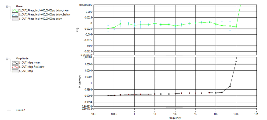
I attached an old measurement (2012) of S_sim @ 4mA of my actual device. Phase is already delay compesated
Henrik
LV since v3.1
“ground” is a convenient fantasy
'˙˙˙˙uıɐƃɐ lɐıp puɐ °06 ǝuoɥd ɹnoʎ uɹnʇ ǝsɐǝld 'ʎɹɐuıƃɐɯı sı pǝlɐıp ǝʌɐɥ noʎ ɹǝqɯnu ǝɥʇ'


