- Subscribe to RSS Feed
- Mark Topic as New
- Mark Topic as Read
- Float this Topic for Current User
- Bookmark
- Subscribe
- Mute
- Printer Friendly Page
NI LabVIEW Modbus API Discussion
09-19-2013 11:58 AM
- Mark as New
- Bookmark
- Subscribe
- Mute
- Subscribe to RSS Feed
- Permalink
- Report to a Moderator
Hey Nishant,
My first recommendation is that for something simple, it really is worth it to use the Modbus I/O servers included in LVRT and LVDSC. If you have either of those products you can use the I/O servers. The benefit to this is that it provides a background process which handles the modbus for you--you just need to look up the registers that your slave sensor is using and it will work.
This library is useful if you need lower level control. In the case of Tarsel, he is trying to test a slave device he created. In my case, I've used the library to meet my performance needs. If you need either low level control or higher performance, you can and should use this library, but you'll need to basically do the following:
- Use your sensor manual to find out the register addresses of the data you want to read, as well as the type. For example, if it were a thermocouple you might have a single register (30001 or 300001 would be the Input register at address 0) which just has the raw ADC value, a U16 or I16. Or, the sensor might provide a floating point value, which would take two registers (Single=32 bytes=2x16-bit modbus registers). In that case you might see something that says TC0: 30001-30002.
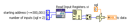
- Once you know the data you need, you'll have to convert it. In the case of a raw value, you'll have to figure the scaling out based on the sensor manual and any calibration values provided. In the case of a floating point value, its probably already done the scaling but you still need to convert the two U16 registers into a single float. That would look something like this:
However, the fun part about bit-level manipulation is that some devices return data in big-endian format and others return it in little-endian format. The modbus standard specifies that each byte is transferred a certain way, but some devices will swap the registers. So instead of the above, it might look like this: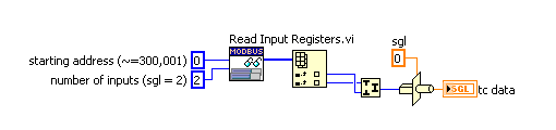
- Finally, you'll have to figure out how to pass that data to the rest of your code, or drop this function in-place in your main loop, depending on your needs. Just remember that on the master side, reads are blocking and can be slow, depending on your network and protocol.
09-23-2013 10:56 AM
- Mark as New
- Bookmark
- Subscribe
- Mute
- Subscribe to RSS Feed
- Permalink
- Report to a Moderator
Hi all!
Is there any more detailed tutorial on how to use this library? I see those examples, but still have no idea where to start from 
Problem description:
I have NI 9871 module, with 5 devices (ABB network analyzers DMTME-I-485) connected in series via RS485 in a single NI 9871 port (Port 1). Each of these devices are assigned with unique address 1-5 (via device settings), and I'm trying to read some values from these analyzers (in device communication protocol manual, it says that holding registers are starting from address 0). However, I don't know what is the procedure: do I have to initialize slave device, or do I have to initialize the master device first, how to show obtained values on front panel (i tried to create indicator, but without any success), who sends the read query - labview application on my crio or initialized master etc.
Thanks in advance!
Best regards,
Marko Gulin
09-23-2013 12:06 PM
- Mark as New
- Bookmark
- Subscribe
- Mute
- Subscribe to RSS Feed
- Permalink
- Report to a Moderator
mgulin wrote:
Hi all!
Is there any more detailed tutorial on how to use this library? I see those examples, but still have no idea where to start from
Problem description:
I have NI 9871 module, with 5 devices (ABB network analyzers DMTME-I-485) connected in series via RS485 in a single NI 9871 port (Port 1). Each of these devices are assigned with unique address 1-5 (via device settings), and I'm trying to read some values from these analyzers (in device communication protocol manual, it says that holding registers are starting from address 0). However, I don't know what is the procedure: do I have to initialize slave device, or do I have to initialize the master device first, how to show obtained values on front panel (i tried to create indicator, but without any success), who sends the read query - labview application on my crio or initialized master etc.
Thanks in advance!
Best regards,
Marko Gulin
I have found my approach to be pretty robust (using the old Modbus Library - cRIO being the Master / Client - other devices being the Slave / Server).
Timed loop with case statement within. Three states Dial, Talk, Hangup.
Dial state: TCP Open Connection FB (Or the equivalent in this library), pass the refnum to a shift register to be used by subsequent states. If no errors, go to Talk State - otherwise go to Hangup state.
Talk state: Initialize arrays outside of the timed loop and wire them in. MB Ethernet Master Query FBs (Read and Write flavors, again equivalent FBs from this API) If no errors, go to Talk state. Otherwise, go to Hangup.
Hangup: TCP Close Connection FB - and back to Dial State
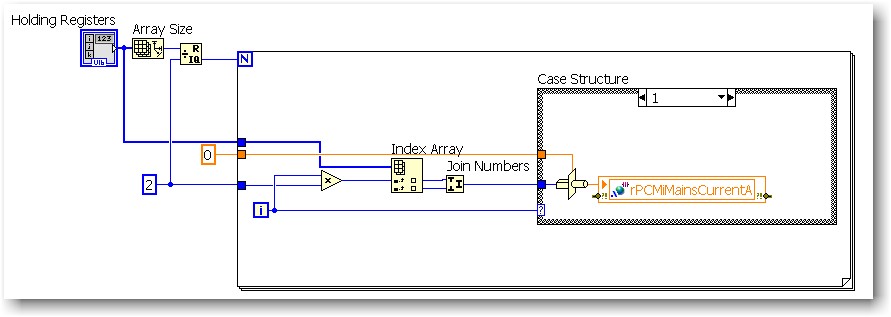
For unpacking the array, a For loop tied to the returned array's size and combine / manipulate the U16s as required.
Message was edited by: S1ack
09-23-2013 11:22 PM
- Mark as New
- Bookmark
- Subscribe
- Mute
- Subscribe to RSS Feed
- Permalink
- Report to a Moderator
mgulin wrote:
Hi all!
Is there any more detailed tutorial on how to use this library? I see those examples, but still have no idea where to start from
Problem description:
I have NI 9871 module, with 5 devices (ABB network analyzers DMTME-I-485) connected in series via RS485 in a single NI 9871 port (Port 1). Each of these devices are assigned with unique address 1-5 (via device settings), and I'm trying to read some values from these analyzers (in device communication protocol manual, it says that holding registers are starting from address 0). However, I don't know what is the procedure: do I have to initialize slave device, or do I have to initialize the master device first, how to show obtained values on front panel (i tried to create indicator, but without any success), who sends the read query - labview application on my crio or initialized master etc.
Thanks in advance!
Best regards,
Marko Gulin
Hey Marko,
I think S1ack did an excellent job of describing the basic process for using the code--a state machine of some form or another really is usually the best way to handle modbus, simply because it is a network process. The function he described is also what we'd use for normal TCP or UDP, so it makes sense to do the same with modbus.
To give you a slightly different view, I wanted to point out a few things:
- The code is divided along the concept of an "instance", or stand-alone copy of the code/data-space associated with your modbus device.
If you are implementing a slave, this means that each instance creates a new fairly robust daemon, the mechanisms to start or stop that daemon, and the modbus dataspace (in the default implementation, which follows the specification, this means 65k holding registers, 65k coils, etc...). Creating a 2nd slave instance makes a new daemon and dataspace
If you are implementing a master, the only thing an instance does is wraps a connection reference. That is, when you create a master you are generating a connection to some slave. Masters do not have a dataspace, so the only "instance" information we have is the connection. - The process is different depending on if you are doing TCP or serial. For TCP, you need a listener in order to open a connection, meaning that your "Create Master Instance" function can quite easily fail--which is, perhaps counter-intuitively, a positive thing. Failures we know about are good!
You are using serial, however, which has fewer checks in place. Here, "opening a connection" has no meaning--TCP is already a high-level protocol, but serial is not. Instead, you simply notify the NI-VISA driver that you wish to talk on your serial port with certain configurable settings. The assumption/hope is that there is a device on the other end. - To more directly answer your question, the process will be:
For a slave: Create a slave instance, poll the data space for changes (via Read/Write functions on the palette). For specialized behavior, our eventual goal would be to more easily expose the "data model" functionality and allow people to add event-based mechanisms to their code, but for now the behavior is pretty much fixed to polling.
For a master: Create a master instance, poll the data space for changes (via Read/Write functions on the palette). On the plus side, this is pretty much the same as the slave. On the down side, there is no "event-based" option for the master, because Modbus was developed with a request-response architecture in mind. That is, the master is the event. - As somewhat described in the previous statement, both the slave and master can modify the dataspace. However, the master (or Master Instance) is the one that generates the query. This and other information can be found here: http://www.ni.com/white-paper/7675/en
- Finally you mentioned putting an indicator on the data. I think we would need more information to help you out there. You should be able to put an indicator on the data output of each method without much difficulty. The only issue would be casting the booleans/U16s to a more meaningful data type (see post 40, or below).
Not to sound like a broken record, but I would highly recommend you contact our support or sales staff and talk to them about modbus I/O servers. I/O servers have their disadvantages, but for the most common use case they are well worth the money--especially if you already have LabVIEW Real-Time or DSC. For example (from the help: http://zone.ni.com/reference/en-XX/help/371618J-01/lvmve/dsc_modbus_using/ ) you can specify a shared variable as being bound to a single-precision floating point register F3000046 and simply read (or write) that value in the code. To do the same with this library, you'd have to follow the process outlined in post 40 above.
09-24-2013 07:49 AM
- Mark as New
- Bookmark
- Subscribe
- Mute
- Subscribe to RSS Feed
- Permalink
- Report to a Moderator
S1ack, smithd,
First, thank you for your quick and excellent answers! I have one more question - since NI MAE (Measurement & Automation Explorer) cannot list slaves connected in certain COM port, is there any other way to check whether or not slave is alive? I have 4 slaves all connected in a single COM port and assigned (by device settings) with unique address 1-4. I'm afraid that slaves are not properly connected, but couldn't find the way how to check this in LV, i.e. I tried to initialize slave with some random address (lets say 50), and program didn't threw any warning/error, e.g. "slave could not be found".
Also, I checked devices factory settings (baud, parity etc.), and they all agree with the ones in MAE for COM port they are connected in.
P.S. I found out that we have install Modbus I/O Server on our cRIO 9074 - what would you suggest that we use for reading from slaves (i.e. devices) - MODBUS library or Modbus I/O Server?
Thank you!
Best regards,
Marko.
10-03-2013 10:42 PM
- Mark as New
- Bookmark
- Subscribe
- Mute
- Subscribe to RSS Feed
- Permalink
- Report to a Moderator
Hi Marko,
Sorry for not getting back to you sooner. The past few weeks have been busy.
I/O vs Lib:
For most basic use cases the I/O server is far better. It has a lot of niceties that the library does not have. However, it is limited in flexibility and performance, which is where the library shines if you use it correctly. If you intend to work your way towards high loop rates, complex architectures, etc...you may wish to start with the library. Otherwise work with the IO server. In my experience the biggest problem occurs not when using one or the other, but when switching. This is because I/O servers have certain usability features, like persistence between system reboots, which then cause problems when people don't realize that those I/O servers they stopped using a month ago are actually still running 
Your core issue:
I notice you said "I tried to initialize slave with some random address". If I could, I want to make it very clear that this library allows you to create a slave instance or master instance. The slave instance would be if you want to use something like a cRIO or PXI chassis as a modbus slave. This is very common in cases where customers want to create a drop-in replacement for their PLC while also allowing for the advantages provided by the cRIO platform. In your case, it sounds like you want 4 master instances. You can generate 4 masters with different Unit ID parameters and use them to speak to all 4 slaves. If you generate 4 masters and still cannot communicate with your slaves, I recommend the following:
- Try using I/O servers or the older library (http://zone.ni.com/devzone/cda/epd/p/id/4756) to communicate
- If you have success, please post back here with any information that might be beneficial in debugging.
- If you still have trouble contact NI support or post on the standard forums (if you do not have a support contract). This means there is something else causing the communication issues.
I'd also appreciate it if you could post back here with your results. I may not have the time to answer, but I'm definitely monitoring this forum and its nice to hear when people have success/failure and why.
Thanks,
Daniel
10-07-2013 01:26 AM
- Mark as New
- Bookmark
- Subscribe
- Mute
- Subscribe to RSS Feed
- Permalink
- Report to a Moderator
Hi Daniel,
I am using your library (LabView 2011) to build up a emulator for equipment I don't have yet. I am running the Master and Slave TCP examples in the library you provided. I am having trouble using "Fetch Input Registers" in the Master. I use "Write Multiple Input Registers" in the slave, and increase the base address (0=30001) to write to registers in the 30001-32000 range, with an input register of 100 U16 values. The "Fetch Input Registers" in the Master does not seem to be able to retrieve anything other than the first 125 U16 registers. Starting addresses <125 show data up to 125. Setting the number of inputs >125 causes disconnection, with the following errror message.
"Disconnected
Error 1 occurred at SubVI in TCP Master.lvclass:Protocol Write.vi:1->IP Data Unit.lvclass:Write ADU Packet.vi:1->Modbus Master.lvclass:Read Input Registers.vi:1->SIM_Modbus_Master.vi"
I suspect I am missing something basic.
Thanks,
Dave
10-07-2013 06:39 AM
- Mark as New
- Bookmark
- Subscribe
- Mute
- Subscribe to RSS Feed
- Permalink
- Report to a Moderator
DWS23 wrote:
Setting the number of inputs >125 causes disconnection, with the following errror message.
Thanks,
Dave
Pretty sure that is close to or at a Modbus limitation.
You will have to create another n fetch commands, in 125 word blocks, to read more than 125 words of data.
Maximum Number of Addresses Which Can be Read or Written at Once:
The modbus protocol specifies the maximum number of addresses which can be read or written at one time. This limits the amount of data which must be transferred in a single command to no more than 255 bytes. For a read command, the limit is 2000 coils or discrete inputs or 125 registers. For a write command, the limit is 1968 coils or 123 registers.
10-07-2013 05:55 PM
- Mark as New
- Bookmark
- Subscribe
- Mute
- Subscribe to RSS Feed
- Permalink
- Report to a Moderator
Thank you. I had missed that. Understanding this also cleared up my other issues.
10-10-2013 05:04 AM
- Mark as New
- Bookmark
- Subscribe
- Mute
- Subscribe to RSS Feed
- Permalink
- Report to a Moderator
Hi,
I was following the link and VIs attached on : https://decibel.ni.com/content/docs/DOC-30140 .
However each time my customer tried running the code, he was getting the error code 6101.
What could be the possible reason for the same?
Thanks
