- Subscribe to RSS Feed
- Mark Topic as New
- Mark Topic as Read
- Float this Topic for Current User
- Bookmark
- Subscribe
- Mute
- Printer Friendly Page
New FPGA-based power electronics HIL simulators with Field Oriented Control (FOC): FEA-based and variable parameter PMSM motor with FOC control, 3-Phase Induction Motor with Observer-based FOC Control, Advanced Inverter with Fault Insertion
07-28-2014 08:42 PM
- Mark as New
- Bookmark
- Subscribe
- Mute
- Subscribe to RSS Feed
- Permalink
- Report to a Moderator
I'm pleased to announce that our R&D teams have published several new FPGA-based ultra-high speed hardware-in-the-loop (HIL) simulation models with field oriented control example code. They are now available for download at no charge on NI Labs. By posting these for free download on NI Labs (before they are added to the NI Electric Motor Simulation Toolkit), we invite your feedback and comments.
Topics
- AC Induction Motor Constant Parameter Simulator with Observer-based Field Oriented Control System
- PMSM Variable Parameter Motor Simulator with Field Oriented Control System
- Advanced Power Electronics Inverter Model & High Fidelity FEA-based PMSM Simulator
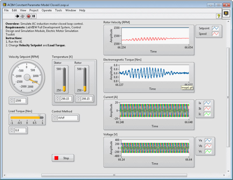
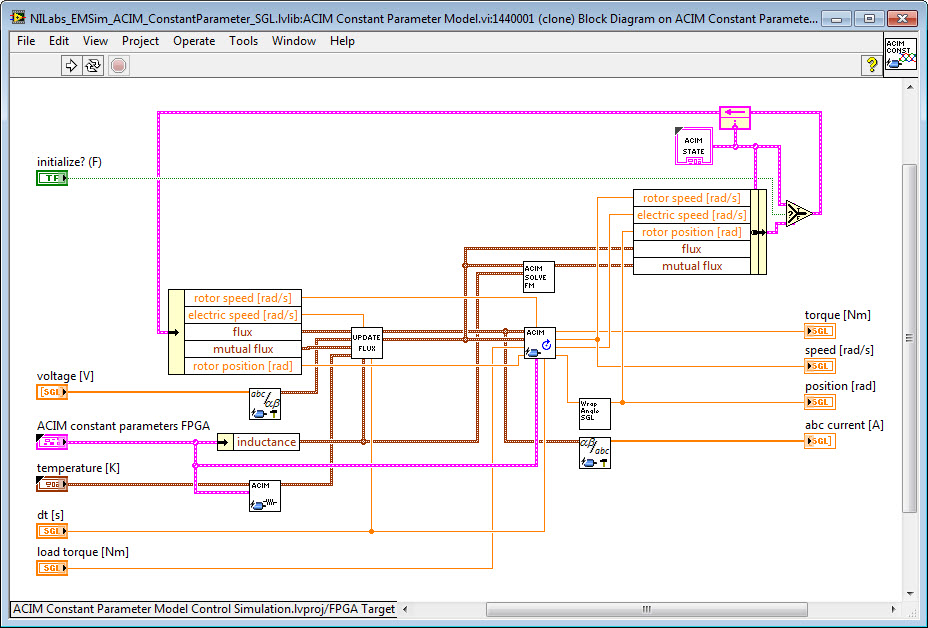
AC Induction Motor Constant Parameter Simulator with Observer-based Field Oriented Control System
The ACIM is the most common motor in industrial motion control systems. Main advantages of the ACIM are simple and rugged design, low cost, and low maintenance. In the ACIM, the electromagnetic induction from the magnetic field of the stator winding generates electric current in the rotor to produce electromagnetic torque. This package contains two examples of simulating and controlling the ACIM.
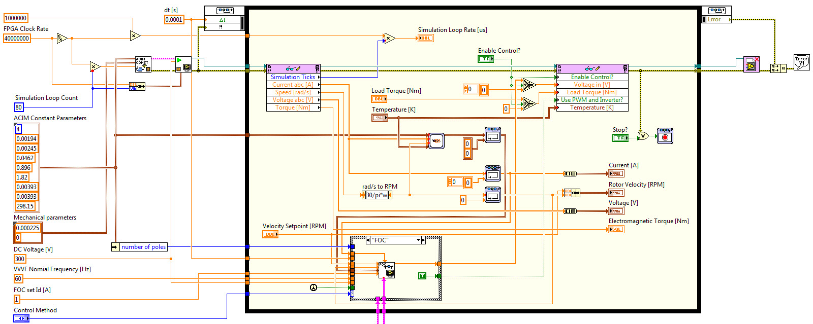
Field Oriented Control System - Top Level
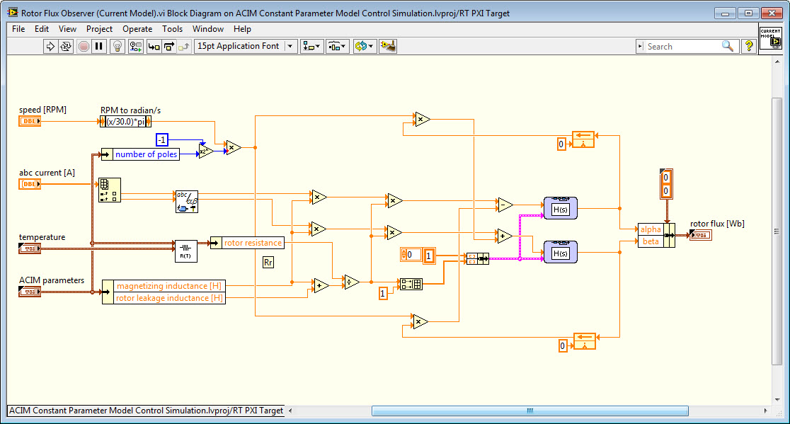
Rotor Flux Observer
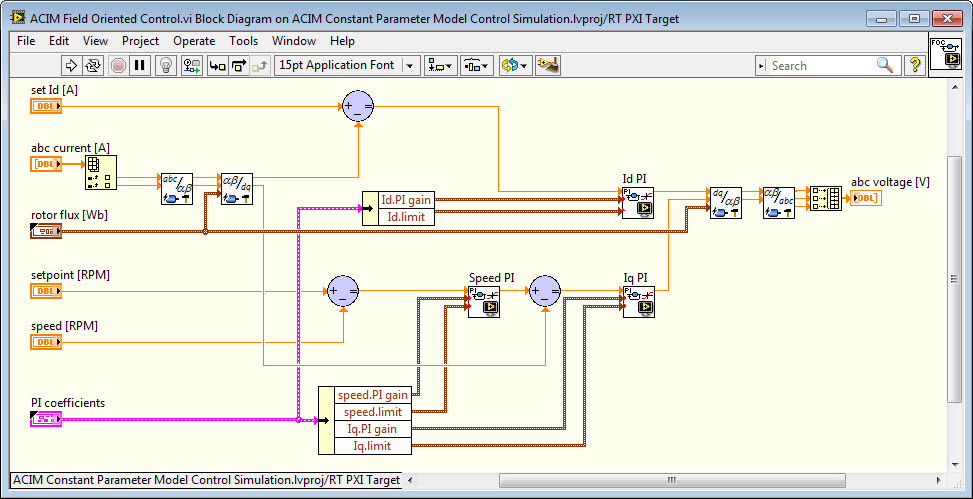
Field Oriented Control Algorithm
FPGA-Based HIL Simulation Model - Squirrel Cage AC Induction Motor
Download AC Induction Motor Constant Parameter Model for NI Electric Motor Simulation Toolkit
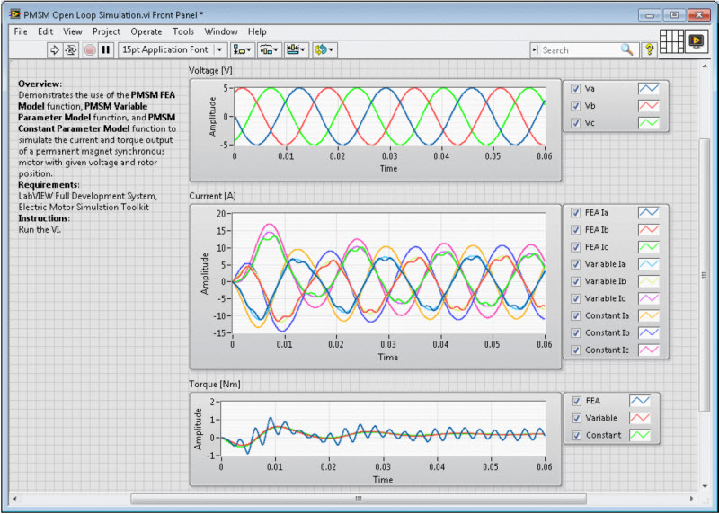
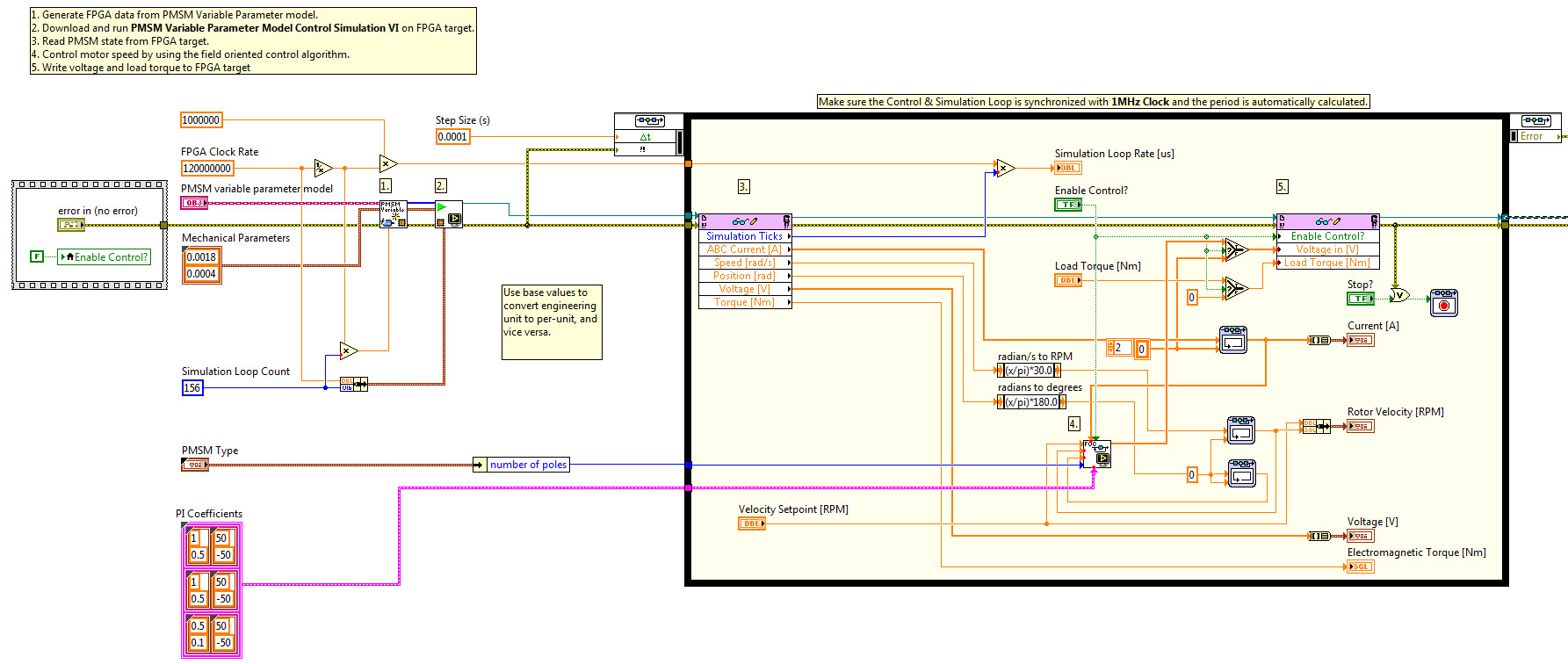
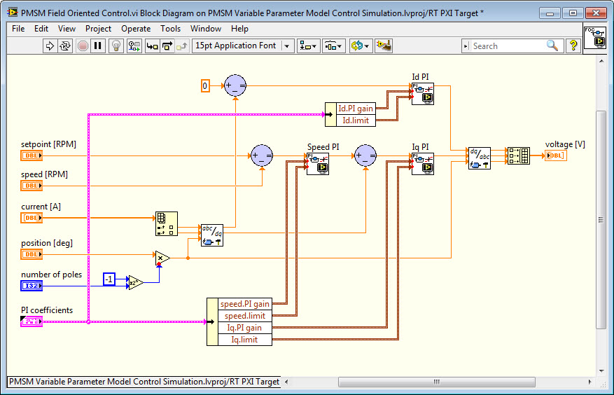
PMSM Variable Parameter Motor Simulator with Field Oriented Control System
The Variable Parameter Model function implements medium-fidelity model simulation. Like the constant parameter model, the variable parameter model utilizes the classic d-q axes mathematical method. The variable parameter model also obtains real motor characteristics from the RTT files like the FEA model. In the variable parameter model, the inductance of a motor varies due to the effect of magnetic saturation. As a result, the variable parameter model renders simulation with higher accuracy than the constant parameter model, and lower accuracy than the FEA model.
Field Oriented Control System - Top Level
Field Oriented Control System - Algorithm
Download the PMSM Variable Parameter Model for NI Electric Motor Simulation Toolkit
Advanced Power Electronics Inverter Model & High Fidelity FEA-based PMSM Simulator
The advanced inverter model allows you to simulate the transient changes of the inverter, which converts direct current (DC) to three-phase alternating current (AC) to supply power to the permanent magnet synchronous motors (PMSM). This model yields simulation with higher fidelity than the ideal inverter model, because it takes into account the forward voltage drop and conductance of the semiconductor power switches within the inverter.
The advanced inverter model also allows you to simulate system behaviors when the inverter has faults. The four fault types are:
• IGBT Open Fault— This fault occurs if any transistor is interrupted. No current flows through the transistor with fault. It is equivalent to replacing the switch with a diode.
• Diode Open Fault— This fault occurs if any diode is interrupted. No current flows through the diode with fault. It is equivalent to replacing the switch with a transistor.
• IGBT and Diode Open Fault— This fault occurs if any transistor with diode is interrupted. No current flows through the transistor with diode. It is equivalent to removing the switch from the circuit.
• IGBT or Diode Short Fault— This fault occurs if any transistor or diode is bypassed. It is equivalent to replacing the switch with a wire. In this case, the protection circuit will turn off the transistor with diode opposite to the one with fault to avoid short circuit to the voltage source.
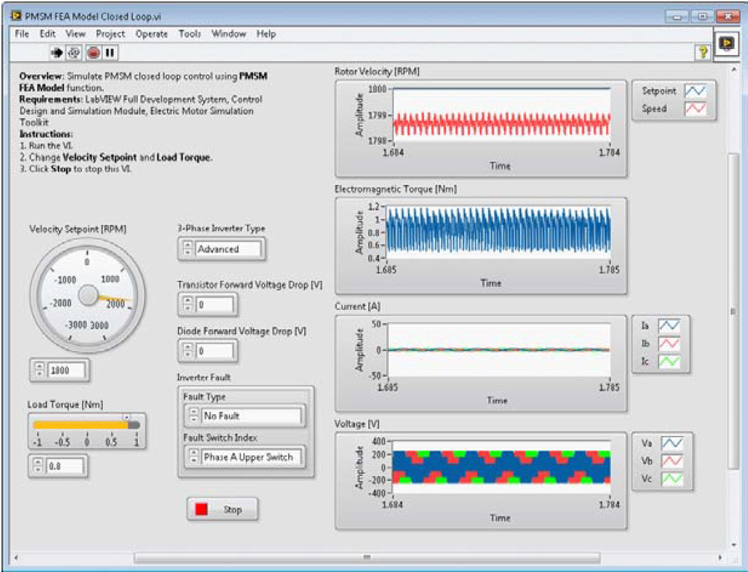
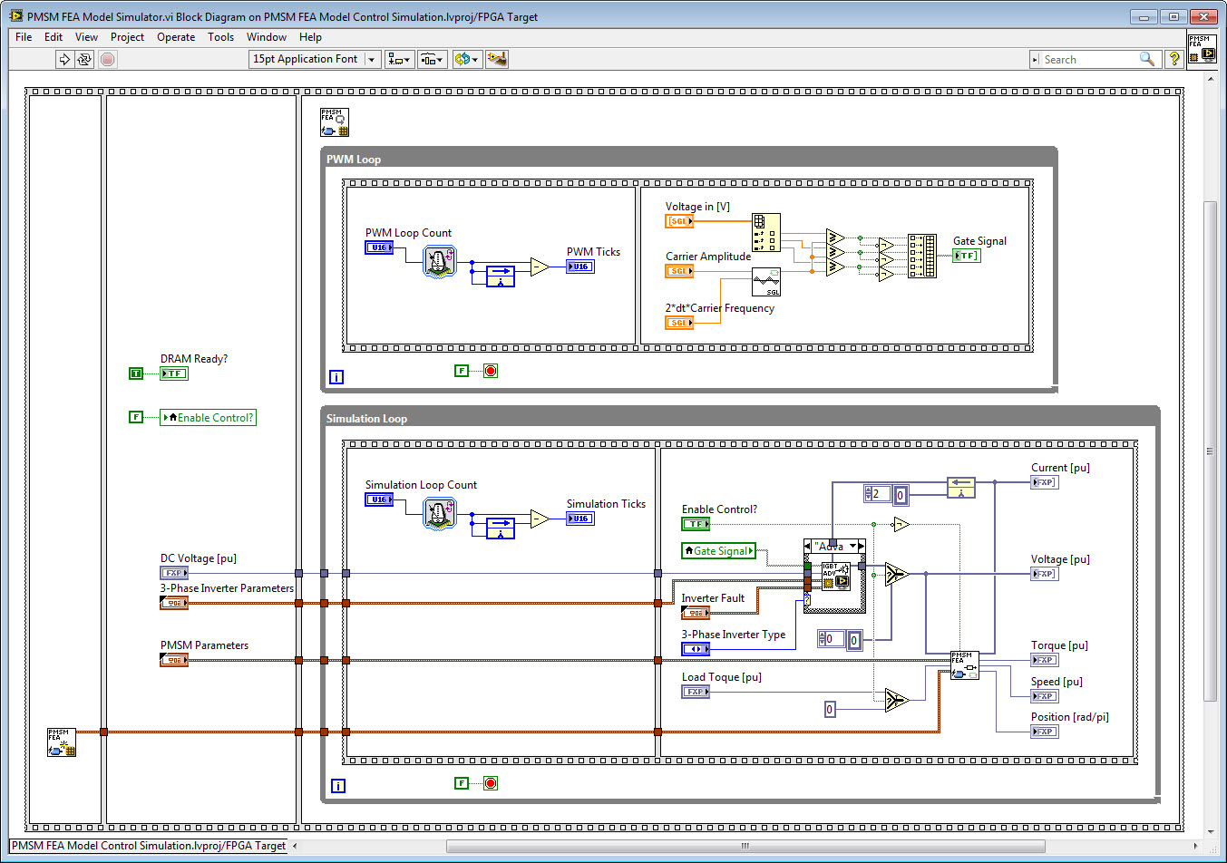
PMSM Finite Element Analysis (FEA) Based Simulator with Advanced Inverter Model
The finite element analysis (FEA) model function implements high-fidelity model simulation. The FEA model takes real motor characteristics into account and uses the FEA method to describe the motor behaviors.
In mathematics, the FEA method is a numerical technique to find approximate solutions to boundary value problems. This method connects many simple element equations over many small subdomains, named finite elements, to approximate a more complex equation over a larger domain. In mechanics and computer science, the FEA method is also a method of mechanical computer simulation and a computational tool to perform engineering analysis. The FEA model uses software programs based on finite element method algorithms to divide a complex problem into smaller elements.
The FEA model function obtains real motor characteristics from the RTT files. Among the characteristics, motor parameters are analyzed using the FEA method. As part of the simulation process, the FEA model function looks up the motor parameters and characteristics in these files.
RTT Files
An RTT file, or the JMAG-RT motor model, is a third-party product provided by the JSOL company. The file, with an extension of .rtt, contains basic motor characteristics, such as the motor type, connection type, and number of poles, and so on, as well as detailed motor parameters information that the JMAG-RT software extracts from an FEA model.
You can either download RTT files at www.jmag-international.com or create an RTT file by using the JMAG-RT software.
Download the Advanced Inverter Model for NI Electric Motor Simulation Toolkit
Thank you to NI R&D for sharing these tools on NI Labs for the developer community. Please download the toolkits and share your questions, comments, feedback and requests!
