- Subscribe to RSS Feed
- Mark Topic as New
- Mark Topic as Read
- Float this Topic for Current User
- Bookmark
- Subscribe
- Mute
- Printer Friendly Page
graph ploting problem in labview multisim cosimulation
04-10-2014 09:01 AM
- Mark as New
- Bookmark
- Subscribe
- Mute
- Subscribe to RSS Feed
- Permalink
- Report to a Moderator
hello,
i have designed a model in multisim labview cosimulation. inside the control and simulation loop of LabVIEW 2012, i want to see output on xy plot but when i attached xy plot (express -->graph indicator-->xy plot),I found that i am able to scroll the x y value but graph is not visible.
please tell me possible proble.
aditya
04-11-2014 12:43 AM
- Mark as New
- Bookmark
- Subscribe
- Mute
- Subscribe to RSS Feed
- Permalink
- Report to a Moderator
Post your vi and multisim file.
04-11-2014 08:47 AM
- Mark as New
- Bookmark
- Subscribe
- Mute
- Subscribe to RSS Feed
- Permalink
- Report to a Moderator
Yes, please do attach your code. It is very difficult to answer technical questions without screenshots and code. To attach files, reply to the thread and click "Use advanced editor" (upper right corner). Then click the Browse... button at the lower left corner to attach your files.
When attaching code, one trick to make sure you include all the necessary subVIs is to go to File>Save As>Duplicate hierarchy to new location. Then copy the Multisim file into the same folder and zip it up.
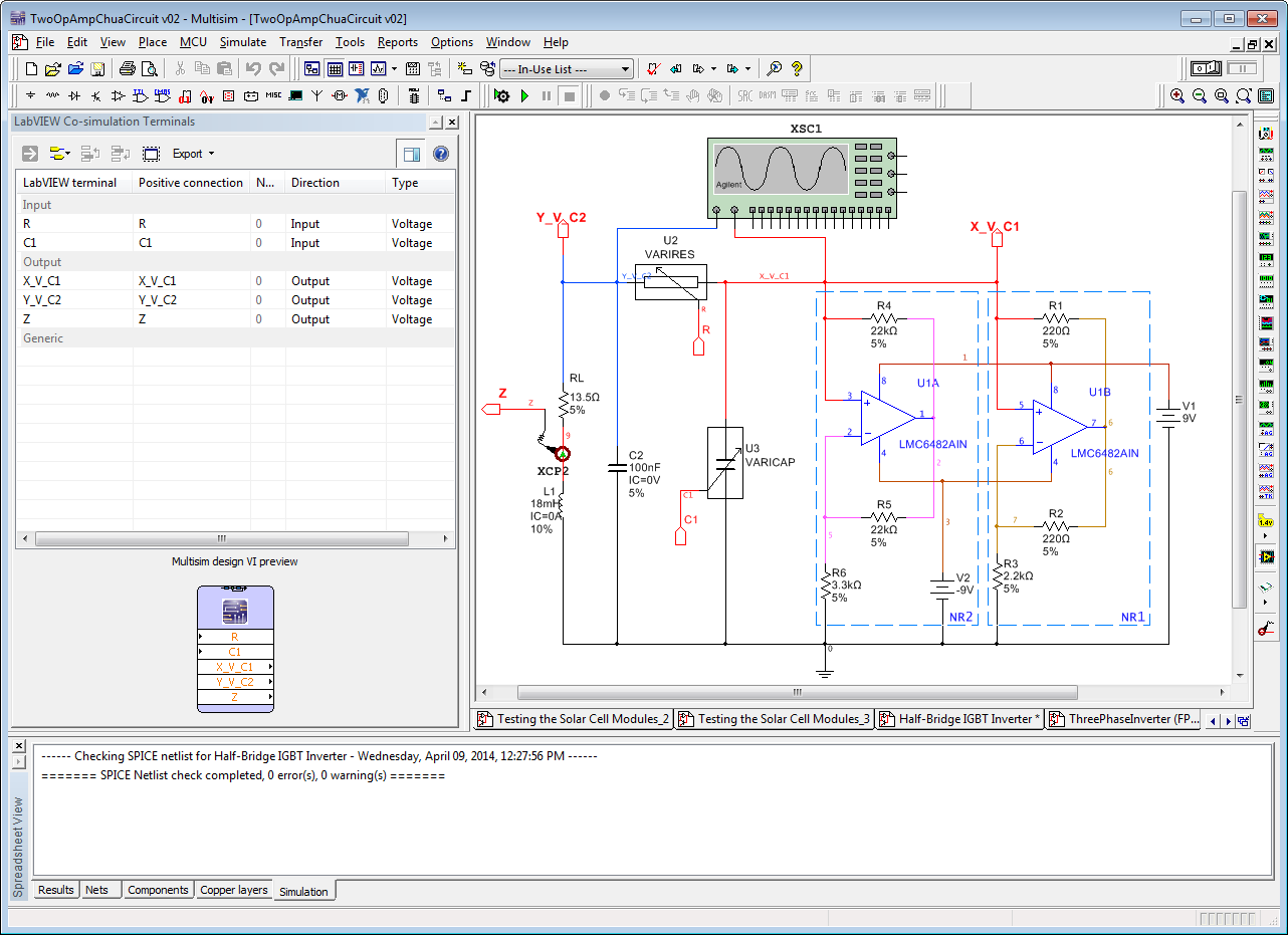
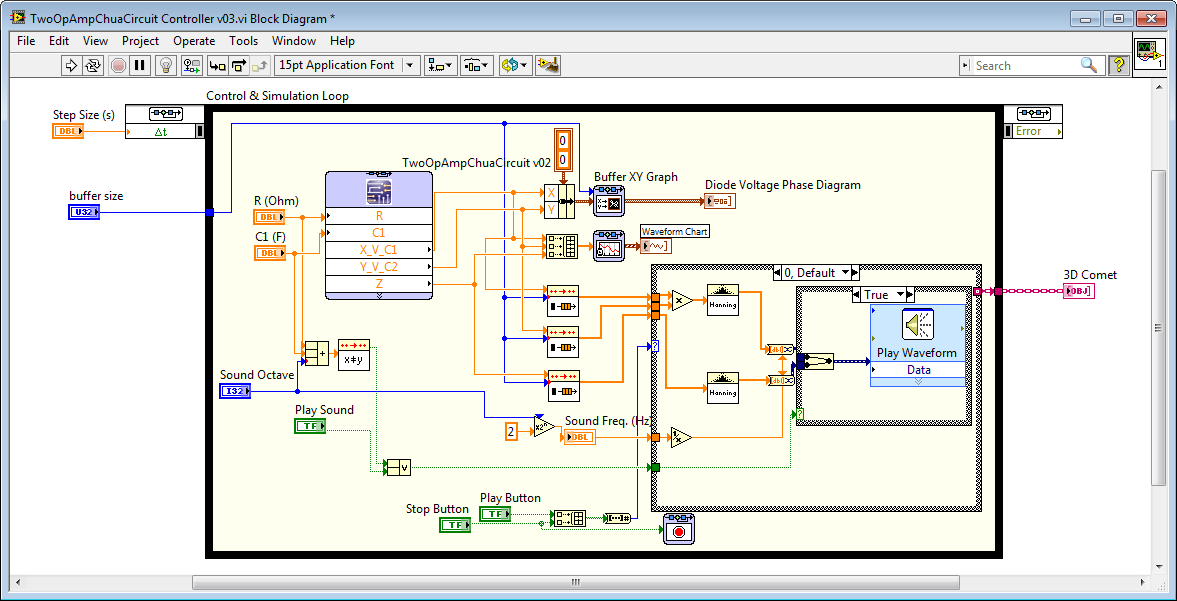
For a good example of XY Graphing with Multisim co-simulation, download the Power Electronics Developer Guide software and take a look at the chaotic circuit examples. These include phase diagram graphs implemented with XY Graphing (top left graph below).
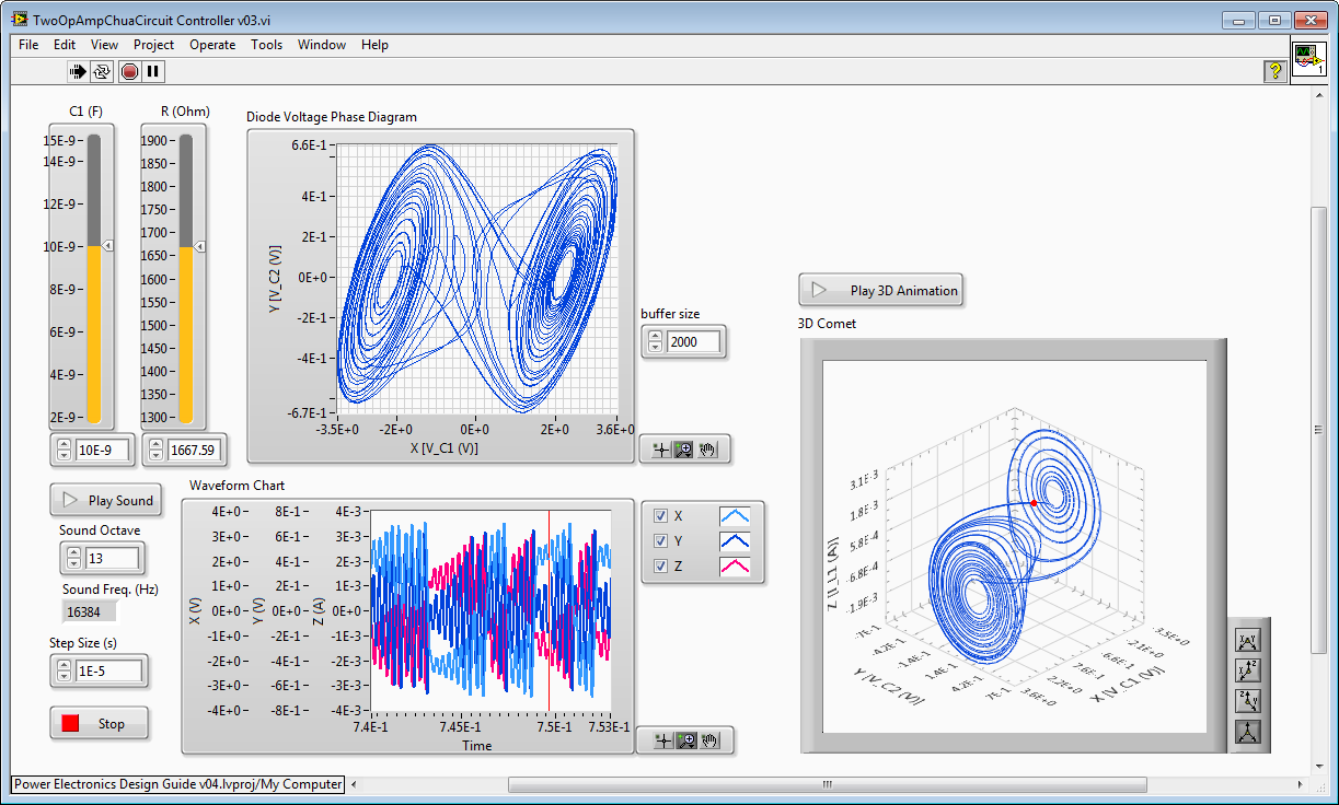
To do XY graphing within the NI Control Design & Simulation loop, the trick is to use the Buffer XY Graph function (top center of screenshot below). You can find this on the palette at Control Design & Simulation>Simulation>Graph Utilities>Buffer XY Graph. The reason is that if you are doing a continuous time (variable timestep) simulation, you don't want to graph the results on minor timesteps. That's why there are special graphing/charting functions for the simulation loop.
Technical Explaination: Under the hood, continuous time blocks can actually be executed multiple times on each simulation timestep as the solver automatically makes adjustments to satisfy your accuracy constraints. This enables the simulator to automatically "slow down" during in-rush/short circuit/transient events to simulate them accurately and automatically "speed up" when the circuit is in more steady state operation. Otherwise, you are forced to select a fixed timestep for the entire simulation, which may not be sufficiently small to correctly simulate fast transient events. Worse, the solver doesn't tell you that the simulation results are incorrect. This is a problem with most co-simulation tools, which only allow fixed timesteps when simulating in combination with embedded code. (Most tools only allow variable timestep simulations when used stand alone- not in co-simulation.) For more information, see the paper below:
See the Power Electronics Developer Guide for more tips and tricks like this. However, keep in mind that NI no longer recommends copying LabVIEW FPGA code into the Control Design & Simulation loop for co-simulation purposes. For a variety of technical and workflow reasons, we strongly recommend you download LabVIEW 2013 Service Pack 1 or higher (ni.com/trylabview/) and use the new Desktop Execution Node. See the new GPIC Reference Design and Training Workshop Software for examples.
