ni.com checkout is currently experiencing issues.
Support teams are actively working on the resolution.
ni.com checkout is currently experiencing issues.
Support teams are actively working on the resolution.
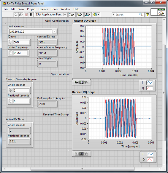
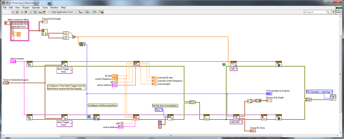
This example combines two shipping examples and eliminates some redundant function calls.
See the following shipping examples for reference
niUSRP EX Rx Finite Sync.vi
niUSRP EX Tx Finite Sync.vi
I'm trying to run this example with two usrp 2921's. I'm not able to receive anything unless i do a continuous transmission, and then it is also not synchronised anymore. Any help on how to modify it for two usrp's?
Hi ErikL, Thanks for your response. I edited it somewhat to work with the 2 usrps, specified different IPs and used a loop for the transmit so that i could do a continuous transmit but receive once. Actually the idea is that i would like to be able to extract only the useful data- in this example the sine and discard the delay. I thought maybe this was a god place to start, but my acquired signal doesn't have a constant starting point. So i'm wondering if there is a way i could go about it. Thanks.
I am using Labview 2009 version. Could I use this version to work on with USRP N210.
I am trying this example using a USRP 2920 but most of the times the received signal is different than the original like the image below..
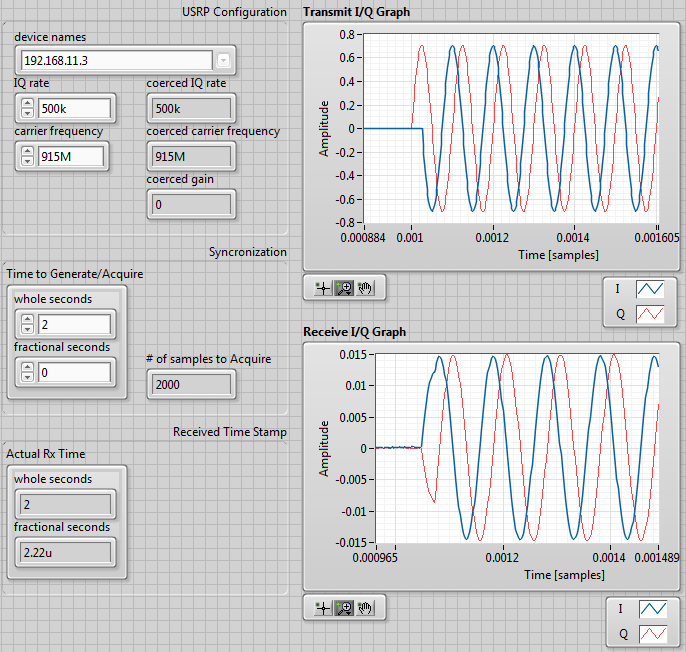
This gets worst when i try transmit a different signal with more changes
I am new with the USRP so maybe I do something wrong..
Any tips or advises how to get this correct?
You are doing everything right! The RX signal is a rotated (phase offset) version of the TX signal. The LO's are not shared between TX and RX. The two phases will change every time the LO's retune, but when plotted on an IQ plot they will be rotated versions of one another.
Hi ErikL,
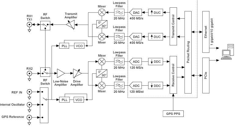
In the reply you mentioned that the rotated(out of phase) is casued by LO arent shared btw TX and RX. But as you can see the USRP RIO 2953R's block diagram below, TX and RX are using the same LO source in the same moduel. Could you explain it? thanks!!!!
Hello, the image shows that there is a delay between Tx and Rx, is there a way to match one to one?
Hi everyone.
I tried the example using USRP N210+CBX 40. But does anyone know why I cannot get the result when I use the frequency range of CBX, which is from 2 GHz to 6 GHz?
The circuit only works at 1.18 GHz and 1.19 GHz. but the frequency range is 2 to 6 GHz.
When I tried to transmit lower than the frequency range of CBX, it rounded the carrier frequency to the lowest frequency of CBX, which I understood. and the result is shown in figure 1.
Then I changed the frequency to 2 GHz with the same IQ rate. The result can be seen in Figure 2.
Then I kept the frequency at 2 GHz but changed the IQ rate to 1 MHz, and the result can be seen in Figure 3.


