- Subscribe to RSS Feed
- Mark Topic as New
- Mark Topic as Read
- Float this Topic for Current User
- Bookmark
- Subscribe
- Mute
- Printer Friendly Page
SCTL clock problem
01-08-2016 11:18 AM
- Mark as New
- Bookmark
- Subscribe
- Mute
- Subscribe to RSS Feed
- Permalink
- Report to a Moderator
Hi,
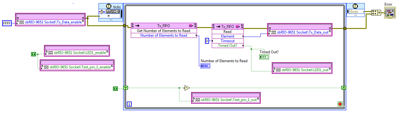
I'm using an sbRIO-9651 with its carrier board and try to execute this simple fpga vi. The SCTL is clocked with a 1MHz external clock. The RT side keeps writing integers in the DMA fifo (Tx_FIFO).
When I probe the Test_pin_1 with an oscilloscope, i'm measuring an unstable square signal with something like 515KHz frequency. Shouldn't it be half the loop clock instead (500KHz) ?
Any idea of what i'm missing.
Thanks
Bachir
01-11-2016 06:23 PM
- Mark as New
- Bookmark
- Subscribe
- Mute
- Subscribe to RSS Feed
- Permalink
- Report to a Moderator
Hi Bachir,
I tried to reproduce something similar with your setup so I created a 1 MHz loop by dividing the 40 MHz base clock on the sbRIO-9651 down by 20 to output the correct clock frequency -- this was all in LabVIEW FPGA (see the below code).
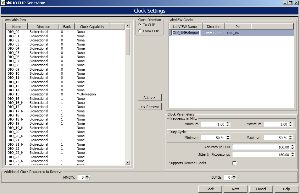
In the sbRIO CLIP Generator, I created an imported clock and specified it to be a 1 MHz clock. This is so I can output a 1 MHz signal and wire feed that signal into my imported clock pin that is an MRCC pin on the sbRIO-9651.

Below is the CLIP Generator configuration for my imported clock.
Questions I have to troubleshoot your setup:
- Have you verified the external clock you are importings is 1 MHz? Is it slightly higher than 1 MHz? Could we see a scope capture of that signal?
- Can you please send a scope capture of the 515 kHz clock output?
If you are generating a clock source from LabVIEW FPGA, make sure it is generating the expected output frequency. For example, if you are using a 80 MHz clock for an SCTL and you divide down by 40 to create a 1 MHz clock, make sure it is actually dividing by 40 instead of 39. That would create an overall output of ~513 kHz which close to your actual result. I doubt this is the cause but wanted to bring it up.
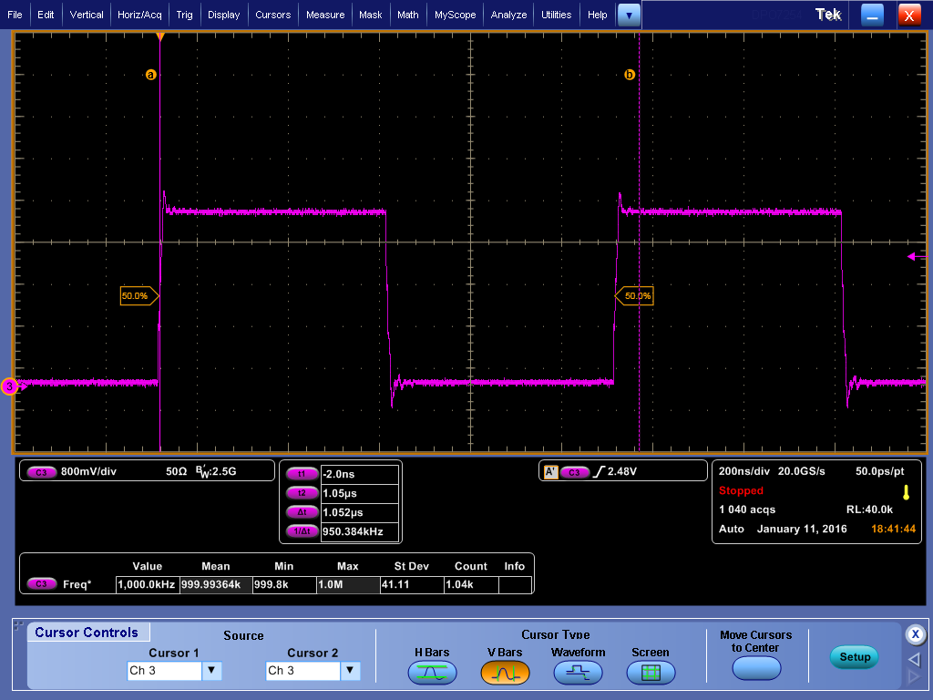
LabVIEW-Created 1 MHz Clock (This signal is not terminated so the SI looks pretty bad).
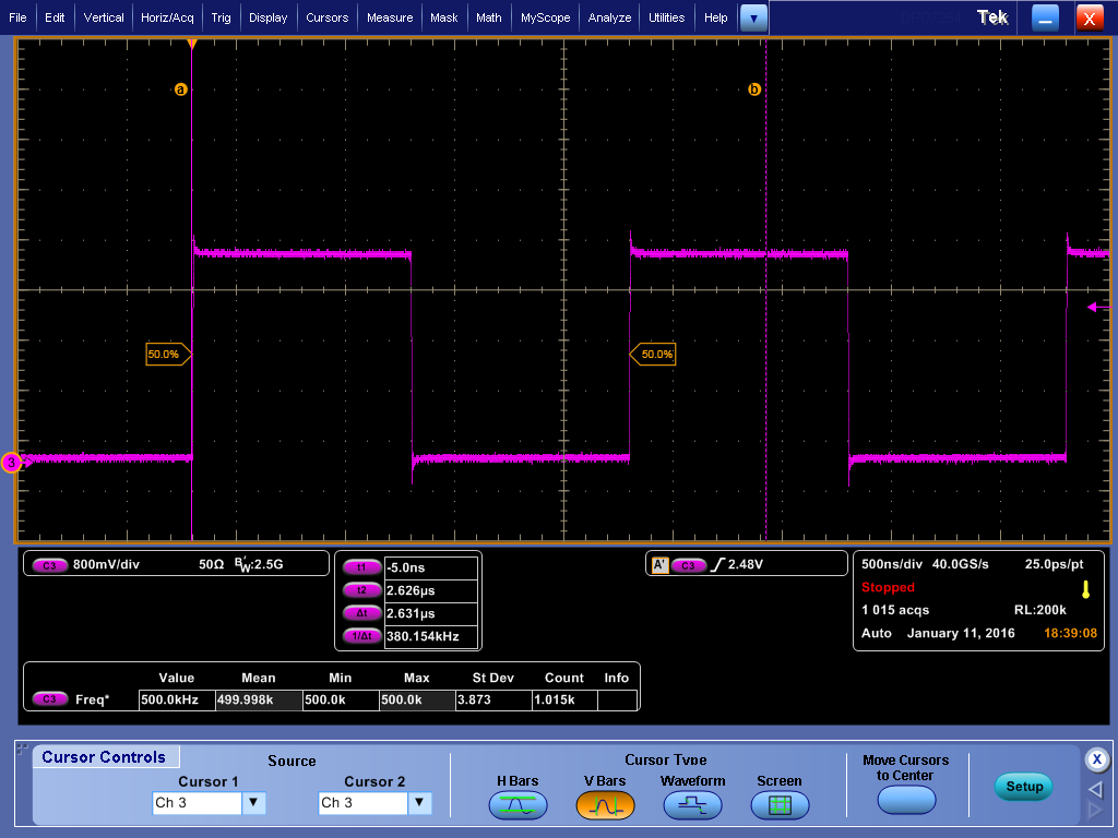
Debug Output on the lower loop running at 500 kHz (This signal is not terminated so the SI looks pretty bad).
Code used to create this example
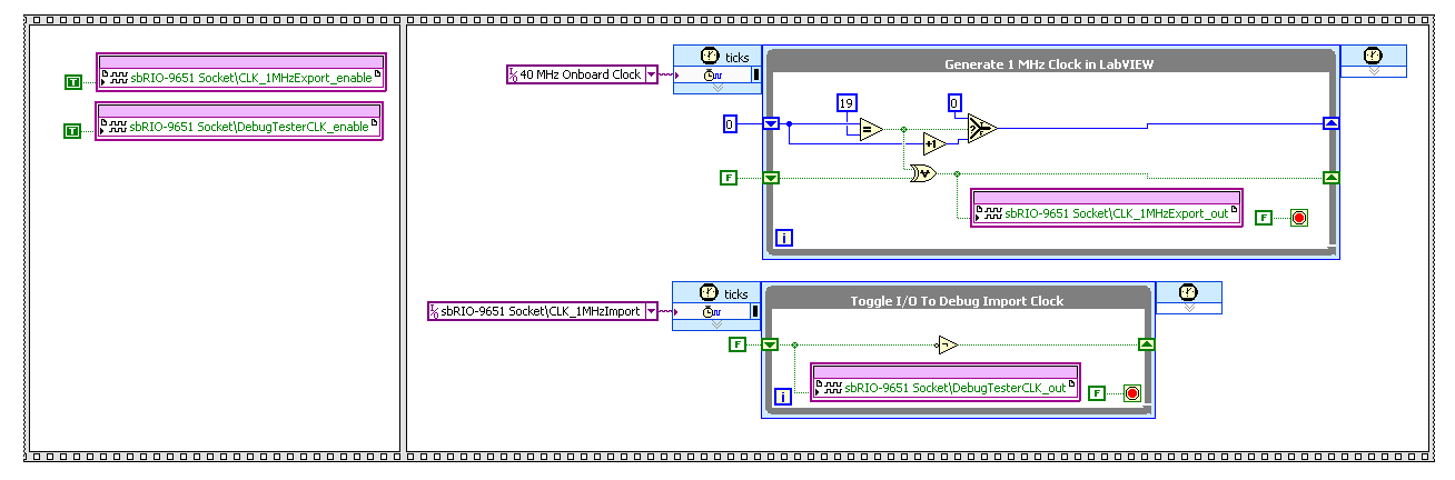
Things to note: I tried mimic your overall architecture to try and reproduce similar results. Ideally, I would set the output enable that corresponds to the lower loop in the same clock domain by creating a simple state machine that first configures the directionality, then goes on to read/write the value. It didn't seem to make a difference in this case but something to consider.
- Tanner
National Instruments
01-12-2016 06:17 AM
- Mark as New
- Bookmark
- Subscribe
- Mute
- Subscribe to RSS Feed
- Permalink
- Report to a Moderator
Thanks Tannerite for your time consuming response.
I replaced my 1MHz clock comming from a external board with one generated by FPGA as you did, and the problem is no longer there.
But i checked that external clock and it was clean and exactly 1MHz( sorry not able to provide images, cause i use an old Tektronix oscilloscope).
Another experience i did is that when i remove the (Tx_Data_out) port cables between the two boards, the problem is also no longer there.
So i come to a conclusion: maybe it's a hardware problem, because the two boards (SOM carrier board and my external board providing the clock are interfaced using only simple cables carrying the clock and data (Tx_Data_out). Therefore i think some interference or comon mode problems between the two boards might cause this problem.
Indeed, on the oscilloscope, the clock signal has a lot of glitches.
Bachir
01-12-2016 08:40 AM
- Mark as New
- Bookmark
- Subscribe
- Mute
- Subscribe to RSS Feed
- Permalink
- Report to a Moderator
Bachir,
I see -- that sounds like a very possible conclusion. Though the 1 MHz source is clean, what really matters is that the clock signal is clean at the sbRIO-9651 that is receiving it. If there are glitches and poor signal integrity, there are no guarantees that the clock will behave correctly inside the FPGA.
- Tanner
National Instruments
01-12-2016 09:55 PM
- Mark as New
- Bookmark
- Subscribe
- Mute
- Subscribe to RSS Feed
- Permalink
- Report to a Moderator
Sometimes it not about the clock speed you are using, a 1kHz clokc might have a 20ps rising time, which will make the clock contain very high frequency element.
So if you still need to communicate with two som, other then check your signal transfer path for impedence matching, you might find change how FPGA driven the signal helpful, in the 8mA driven tab, you can change the suitable driven current, if you see too much overshoot, it might help if you set driven current to 4mA.
Just a tip, it might help, but overall it all about parameters of your signal transfer path.
