- Subscribe to RSS Feed
- Mark Topic as New
- Mark Topic as Read
- Float this Topic for Current User
- Bookmark
- Subscribe
- Mute
- Printer Friendly Page
Pop quiz! Test your understanding of channels!
08-18-2015 03:57 AM
- Mark as New
- Bookmark
- Subscribe
- Mute
- Subscribe to RSS Feed
- Permalink
- Report to a Moderator
*Rambling mode on* 
I think the most intuitive solution would be to fully adopt the real-world analogy; wireless communication. Just drop the idea of a channel "wire".
Sure, there are plenty of ways to achieve "wireless comms" already. There is a plethora of solutions within the language/IDE itself, but it is still perhaps the most frequently developed add-on. This is a symptom of how it is not truly adopted at the lowest levels of the language. Perhaps Channels are the clearest sign ever.
There has been so much focus on the benefits of wired communication in LabVIEW, and how important it is to teach the users to program in LabVIEW in a way that utilizes the power of the wire. The data flow driven execution, the clarity. At the same time so much effort is spent on achieving "wireless" solutions. Why? The dogma says that it is because we just have not truly understood the benefits of wired communication. The truth is that we have a need for both.
In the virtual world we can keep on using wires to connect things "wirelessly". We do the same while drawing on a piece of paper to visualize how two real.world wireless units are logically linked...But the drawing is still not the actual connection. That drawing is just an aid to visualize *one* aspect of what is going on.
So LabVIEW should still have a way to visualize the logical connections established by wireless channels, but just like the real world still actually needs to have no wires to get wireless communication, we need to be able to work truly wirelessly within LabVIEW as well.
How could something like that be more integrated into the language?
Thinking about it I either end up with something that adopts the multitude of ways wireless communication is handled in the real world - or something that merges it with the virtual world.
Perhaps connections need their own layer(s); connection manager(s) etc.. You could link the block diagram with the connection management layer by inserting reference points (writers and readers if you like), but a user event for example would logically originate and belong to the connection management layer. The block diagram can communicate with the connection management layer to get access from anywhere (i.e. wirelessly), and the connection management layer will provide ways to configure and visualize communication the existing connections, and tap into the communication for debugging.
Who's listening to "Radio 1" right now"? The connection manager will provide a list of (named) reference points, and you can choose to jump to the corresponding diagram location from the connection manager's list. (You cannot do that with a queue today for example). It's as if the radio hosts would know the name and location of anyone listening, and they can choose to stop talking if no one is listening anyway...(With wires you could follow the wire yes, but even that get's tiresome...).
User events you say? Well, there is one defined at the communication layer, so you can link your event structure to it. Just go ahead and add an event case, you can look up the user event from the creation dialogue. 
Another just as big or even bigger question is how all this is introduced without killing the "old" wired communication. Wired communication will still be preferable, but often the best solution loses to the more convenient one. In an ideal world wireless was just as robust as wired. In the real world there are drawbacks too, but the convenience of wireless communication trumphs all.
*Rambling mode off*
08-18-2015 03:59 AM
- Mark as New
- Bookmark
- Subscribe
- Mute
- Subscribe to RSS Feed
- Permalink
- Report to a Moderator
AristosQueue wrote:
Thoric wrote:
Suddenly cycles are permitted! The conflict is difficult to accede.
a) How do you feel about Feedback nodes?
b) Is there anything visually that we can do to draw the connection such that it shows a connection without implying "wire"? The current draw style came about after multiple people said, "you know, that channel doesn't really look like a regular wire; I think I could learn to 'see' it differently." But we may need to go further.
The presence of the 'arrow' or 'Z-1' glyph on a feedback node is sufficient to satisfy my brain that the wire isn't a cycle. It takes a moment longer to interpret the dataflow than an ordinary wire, but technically there's a start terminal and an end terminal, so they're fine with me.
On async wires my eyes track back along the wire for the source or origin. On a feedback node that's the exit terminal (head of the arrow), but on async wires there isn't necessarily one visible. I have to then remind myself how they work. It's just a matter of adjusting my mind to accept these unique pipes. I found the switch to using OOP similarly complex - my brain resisted for years, then suddenly it accepted the principles and now I often see a need for inheritence, DD etc. It just took time.
At the moment I don't think the wire look is sufficiently distinct. As kegghead put it there are now infinite wire colourings with class customisation, so async wires looking a little more rounded (like pipes) doesn't make it particularly easy to distinguish them from the plethora of possibilities. I'm not sure what to suggest though as an alternative. No wires? Dashed wires between the loop boundaries? Ghosted/semi-opaque wires? Three-dimensional wires that 'leave the virtual block diagram surface'?
08-18-2015 07:02 AM
- Mark as New
- Bookmark
- Subscribe
- Mute
- Subscribe to RSS Feed
- Permalink
- Report to a Moderator
kegghead wrote:
AristosQueue wrote:
The current draw style came about after multiple people said, "you know, that channel doesn't really look like a regular wire; I think I could learn to 'see' it differently." But we may need to go further.
They still look like wires to me, and that's my biggest aversion to them. Maybe it's because I do so much object oriented work such that I don't really have an expectation of what a wire looks like.
My first feedback when seeing these was not unlike this, and suggested a new syntactic convention of making Channels vertical wires that nominally flow top to bottom (where bottom to top would be "reverse" dataflow; not prohibited, but not conventional).
@AristosQueue, assuming you still have the top VI, would you rearrange to show stacked loops with vertical channel wires and post a side-by-side screenshot?
08-18-2015 08:58 AM
- Mark as New
- Bookmark
- Subscribe
- Mute
- Subscribe to RSS Feed
- Permalink
- Report to a Moderator
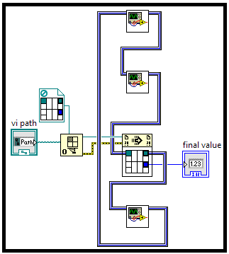
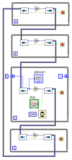
Two different vertical arrangements.
Alpha:
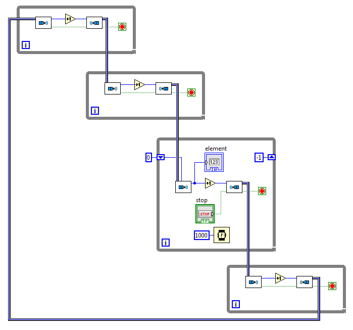
Beta:
08-18-2015 08:59 AM
- Mark as New
- Bookmark
- Subscribe
- Mute
- Subscribe to RSS Feed
- Permalink
- Report to a Moderator
Mads wrote:
I think the most intuitive solution would be to fully adopt the real-world analogy; wireless communication. Just drop the idea of a channel "wire".
That would pretty much defeat the purpose of the feature. The requirement is to solve the problem of the connection path not being visually depicted. The lack of a visual depiction of the transmission path creates problems for understanding code among many users and fails to express the API at conpane boundaries for reusable subcomponents.
Connection managers and the like have been -- and continue to be -- explored. There's a lot of other NI work going into that sort of thing. But none of them directly address the conpane and visual path issues the way channel wires appear to do. The trick appears to be finding a suitable rendering appearance, and different people have different thresholds for "this is different enough that I recognize it distinctively" over to "this is so radically different that it doesn't scan as part of LV". The goal is an appearance that hits that sweet spot for the majority of users.
In short, exploring variations on the visualization of the wire is open to discussion. Abandoning the entire point of the work is a good topic for a separate conversation, but irrelevant here.
08-18-2015 09:04 AM
- Mark as New
- Bookmark
- Subscribe
- Mute
- Subscribe to RSS Feed
- Permalink
- Report to a Moderator
JackDunaway wrote:
My first feedback when seeing these was not unlike this, and suggested a new syntactic convention of making Channels vertical wires that nominally flow top to bottom (where bottom to top would be "reverse" dataflow; not prohibited, but not conventional).
@AristosQueue, assuming you still have the top VI, would you rearrange to show stacked loops with vertical channel wires and post a side-by-side screenshot?
Not sure I see how vertical wires are a unique syntax or particularly distinguishable?
08-18-2015 09:21 AM
- Mark as New
- Bookmark
- Subscribe
- Mute
- Subscribe to RSS Feed
- Permalink
- Report to a Moderator
"Alpha" most typically mimics how I arrange parallel for loops, aligned LHS, but kinking the Channels is unpleasant. Beta avoids the kinks, but starts to look a little more sequential again. I'm swaying between the original horizontal arrangement and Alpha.
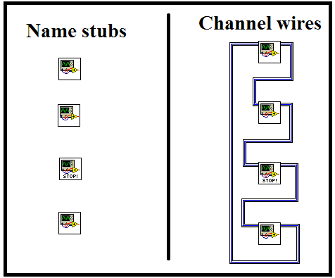
I think a more distinct graphic is required. Channels still look like wires.
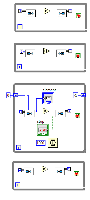
I know labelling them goes against the purpose somewhat, but this works much better for me:
08-18-2015 09:35 AM
- Mark as New
- Bookmark
- Subscribe
- Mute
- Subscribe to RSS Feed
- Permalink
- Report to a Moderator
Here's the problem with the named stubs approach:
08-18-2015 09:37 AM
- Mark as New
- Bookmark
- Subscribe
- Mute
- Subscribe to RSS Feed
- Permalink
- Report to a Moderator
Thoric wrote:
Not sure I see how vertical wires are a unique syntax or particularly distinguishable?
There was discussion at one point that if channel wires were always top/bottom terminals of nodes, the general vertical flow of their code would run orthogonal to the general horizontal flow of regular wires, thereby creating a difference that was totally recognizable. If you think about it, you basically never see in LV a wire where both the source and the sink terminals are top or bottom terminals.
08-18-2015 09:41 AM
- Mark as New
- Bookmark
- Subscribe
- Mute
- Subscribe to RSS Feed
- Permalink
- Report to a Moderator
Fun variant for code reuse: