- Subscribe to RSS Feed
- Mark Topic as New
- Mark Topic as Read
- Float this Topic for Current User
- Bookmark
- Subscribe
- Mute
- Printer Friendly Page
Help with Arduino
10-27-2011 12:57 PM
- Mark as New
- Bookmark
- Subscribe
- Mute
- Subscribe to RSS Feed
- Permalink
- Report to a Moderator
Hello everyone, I am working on a class project using labview with arduino uno to turn on/off a LED and also change the brightness using a virtual slider/knob directly from the VI. I am pretty new to labview so having really hard time. Can anyone suggest how to build the block diagram. I will greatly appreciate your feedback. Thank you.
10-27-2011 02:01 PM
- Mark as New
- Bookmark
- Subscribe
- Mute
- Subscribe to RSS Feed
- Permalink
- Report to a Moderator
Himelspike,
With the "slider" are you referring to some kind of linear potentiometer? So one easy to use way of controlling brightness of a single LED through LIFA is to use PWM to throttle the brightness of an LED. Here is a quick example of doing that:
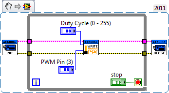
The PWM functionality of LIFA takes advantage of Arduino's analogWrite function which is limited to only the PWM pins of the Arduino Uno.
Try it and let me know how it goes.
-Ben
National Instruments
Applications Engineer
10-27-2011 02:37 PM
- Mark as New
- Bookmark
- Subscribe
- Mute
- Subscribe to RSS Feed
- Permalink
- Report to a Moderator
Thank you so much Ben for your reply. But are you saying that I have to connect a potentiometer to the arduino PWM pin? I was looking for a way to virtually control the brightness from the VI without actually using a potentiometer hardware.. Is it possible ?
10-27-2011 03:01 PM
- Mark as New
- Bookmark
- Subscribe
- Mute
- Subscribe to RSS Feed
- Permalink
- Report to a Moderator
Himelspike,
This method would not need a physical slider. The Duty Cycle of the PWM signal would change the brightness of the LED.
-Ben
National Instruments
Applications Engineer
10-27-2011 05:00 PM
- Mark as New
- Bookmark
- Subscribe
- Mute
- Subscribe to RSS Feed
- Permalink
- Report to a Moderator
The object in the block diagram labelled Duty Cycle ( 0 to 255 ) is your slider. You will need to add a control to your front panel that matches this functionality.
Your LED is connected to PIN 3, In this block digram the output signal driving your LED is a pulse width modulated , PWM signal. When the duty cycle of the PWM signal is low the LED will be dim and when the duty cycle is high the LED will be bright. Duty cycle is the ratio of (On time)/On time + Off time). You will need to add a resistor in series with the LED when you connect the LED to Pin 3. I suggest a 220 ohm resistor. The resistor limits the current through the LED. Excessive current can quickly burn out a LED. Don't forget the ground connection for the LED and the resistor.
Howard
10-27-2011 11:54 PM
- Mark as New
- Bookmark
- Subscribe
- Mute
- Subscribe to RSS Feed
- Permalink
- Report to a Moderator
Yes! It worked. Thank you so much Ben and Howard !!! You guys rock  I never thought I will have my problem solved so quickly !! Amazing
